
Introduction
RACECUBETM is a newly-developed laser-based, highly accurate, wheel alignment technology that through ingenious software offers many advantages over existing systems. Its tablet-integrated algorithms and unique pairing between its Cube-mounted laser and matched target scale bars, means exceptionally accurate vehicle set-ups can be achieved, all without the need for the precise placement of the scale bars fore and aft of the vehicle. It is suitable for vehicles in all categories of 4-wheeled motorsport.
RACECUBETM is capable of an accuracy of +/- 1 minute of a degree of individual toe; +/- 2 minutes of total toe; +/- 5 minutes camber and +/- 8 minutes caster.
Further advantages include: No requirement to remove bodywork or wings; fast to use; easily transportable; calculates the effective centreline and any potential thrust angle; provides means for accurate readjustment of toe angles; is highly repeatable; calculates caster and KPI.
Instructions for use
Getting started
RACECUBE™ is supplied pre-calibrated and is paired with the tablet provided. It is important that a specific Cube and tablet supplied are always used together.
Select Precision Mode
Select the mode for the level of precision required for the Output results. i.e. Expert or Workshop. Workshop mode rounds the results to the nearest 5 minutes of a degree or 0.5mm whereas Expert mode calculates results to the nearest 1 minute or 0.1mm. For many setup requirements the Worshop mode level of accuracy is perfectly acceptable and offers a good compromise between speed of adjustment and acceptable accuracy. For Race Engineers wanting a higher level of precision, the Expert mode is recommended. You can also swap between modes after the measurement data has been recorded and saved.
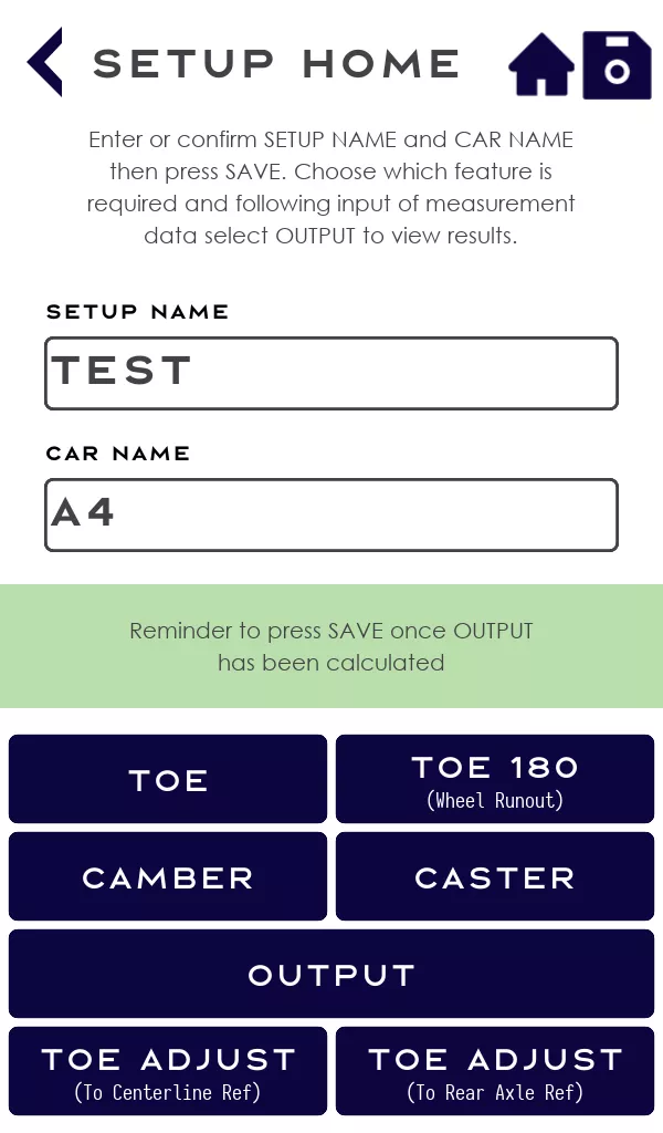
Setup Home
Using the tablet provided, enter a Setup Name and a Car Name, then select the type of measurement to be undertaken: Toe; Toe 180 (Wheel Runout); Camber; Caster; Toe Adjust (Centreline Ref); Toe Adjust (Rear Axle Ref).
General set-up
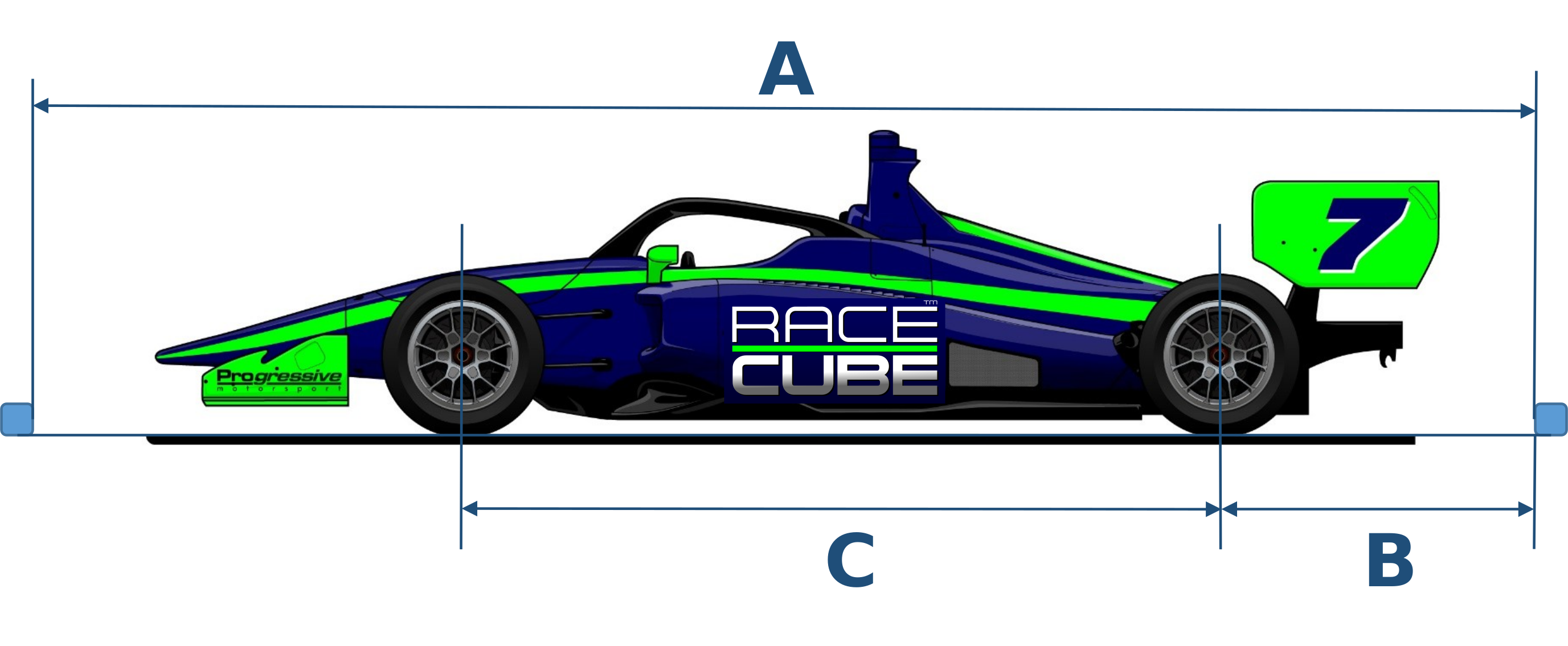
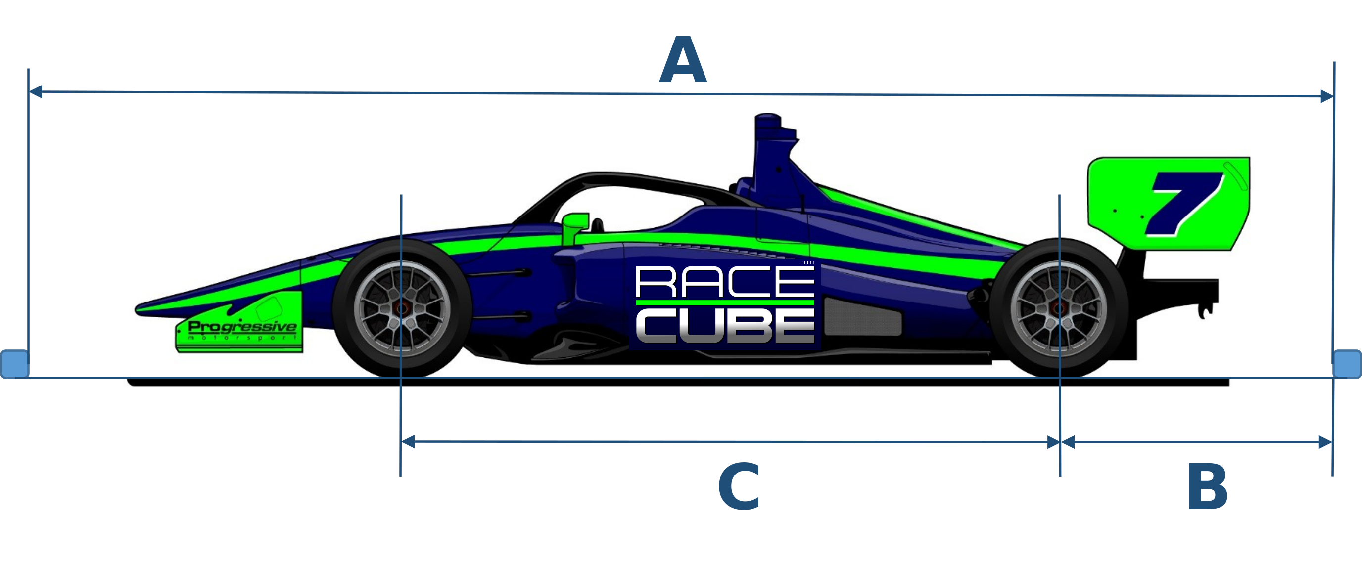
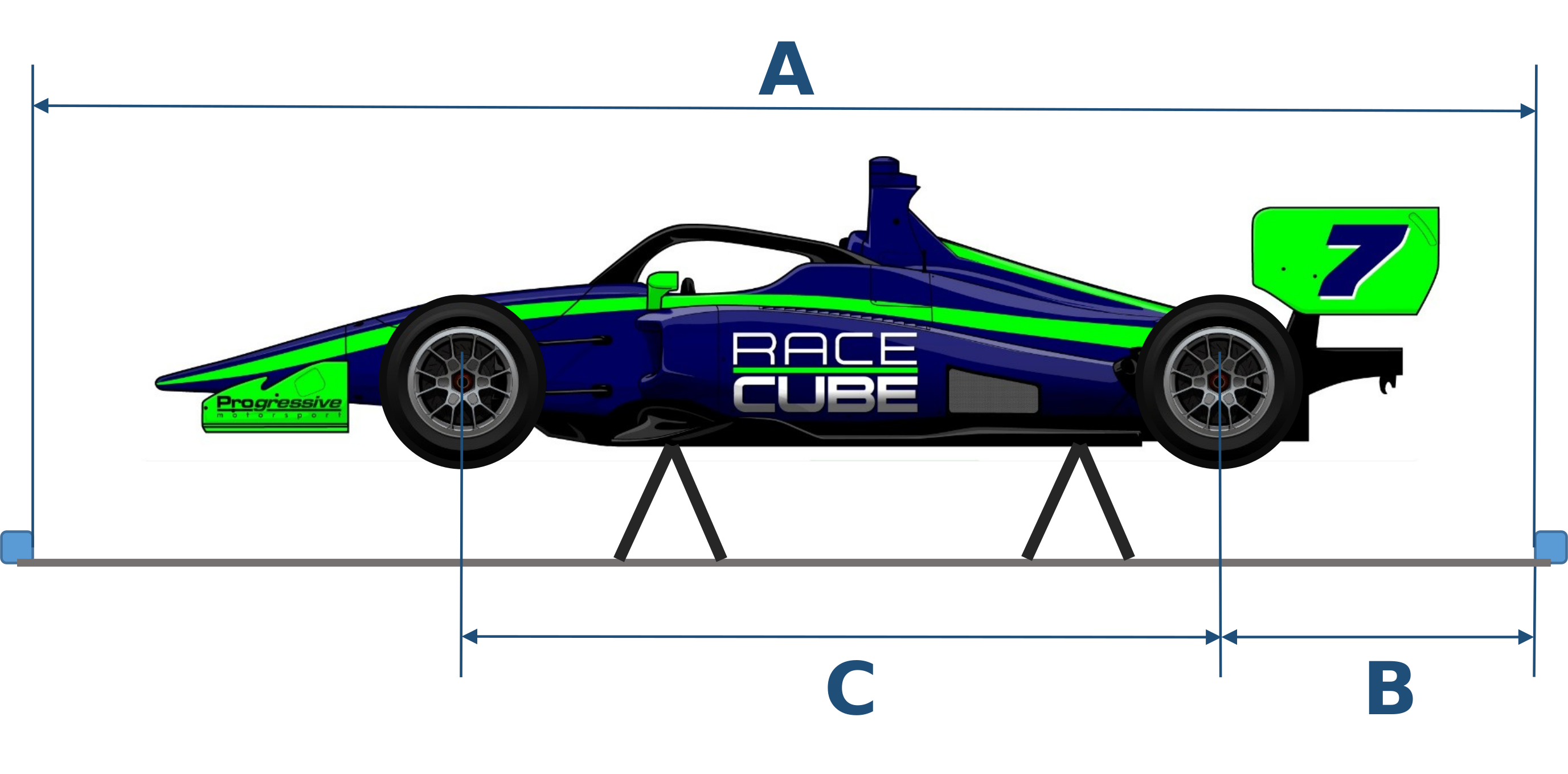
Place the measurement scales at the front and rear of the car and enter values for A, B and C using the steel tape provided. An approximate distance of 1500mm from each axle centreline is recommended but the user can decide. An accuracy of +/- 20mm is acceptable with the bars approximately parallel. The magic of RACECUBE™ means the bars do not need to be precisely positioned.
Tyre selection
Choose the type of tyres on your vehicle and, from the tyre wall information, enter the data requested.
Measure
Initial toe measurement
Assemble the Cube with the most appropriate wheel rim adaptor e.g. The T-bar or Y-bar. Adjust the adaptor if necessary to suit the rim size (T-bar) or wheel nuts (Y-bar). Place the adaptor with the Cube attached against the rim or wheel nuts. Switch on the Cube and align it on the rim/nuts with a fore and aft laser direction.
Launch RACECUBE™ on the tablet and enter a new Setup or retrieve a saved one. Select the type of measurement being undertaken: Toe; Toe 180; Camber; Caster; Toe Align; Toe Align Rear Axle. Click on each wheel position and enter the corresponding laser readings taken from the front and rear measurement scales: Input the corresponding number and letter that the laser crosses on both the front and rear measurement scales. We recommend adopting a logical order for moving from wheel to wheel. E.g. start with Front Right and move around the car clockwise when taking readings.
Initial toe measurement 180° wheel runout
Here you can negate the effects of wheel runout. With both the front and rear measurement scales left unmoved from their original positions, push the car forwards or backwards until the REAR wheels complete half a rotation. Now repeat the Initial Toe measurement procedure and following input of data select the relevant OUTPUT to view the results.
Output
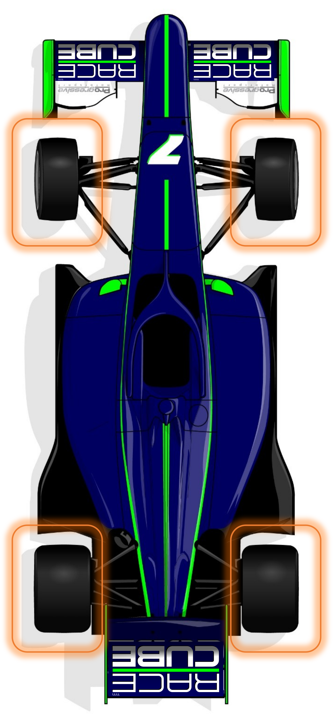
Depending on the RACECUBE™ product purchased, RACECUBE™ Pro Plus or RACECUBE™ Pro, one or two types of output can be obtained: 4Wheel Output presents the results in a traditional sense as the individual wheel toe and total toe values, whereas CUBE Vector Output presents the same results as a function of the total toe and resultant steer vector for both the front and rear axles. The CUBE Vector method also provides a ‘traffic light’ indication of whether the alignment is acceptable or may require adjustment. Should adjustment be deemed necessary, both options use the same ‘Toe Adjust’ function in the software, telling you where to easily adjust the wheels to for a desired target alignment. This can be done relative to the effective Chssis centreline reference or Rear Axle reference.
RACECUBE™ Pro Plus: Switch between 4Wheel Output and CUBE Vector Output.
RACECUBE™ Pro: Select CUBE Vector Output.
Results
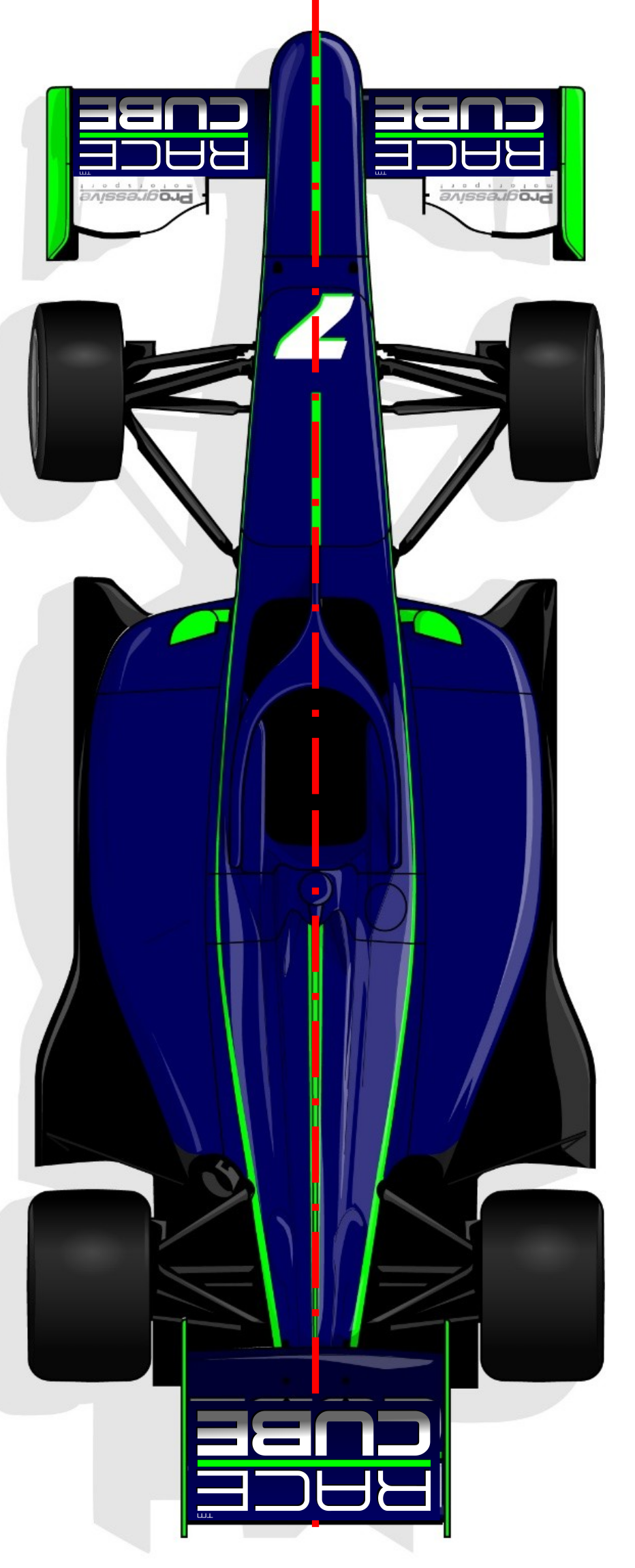
Centreline reference: initial toe measurement output
Here you see all data for each respective car wheel relative to the calculated Chassis centreline reference of the vehicle: i.e. Toe and Runout. As with standard convention, toe-in is ‘+ve’ and toe-out is ‘-ve’.
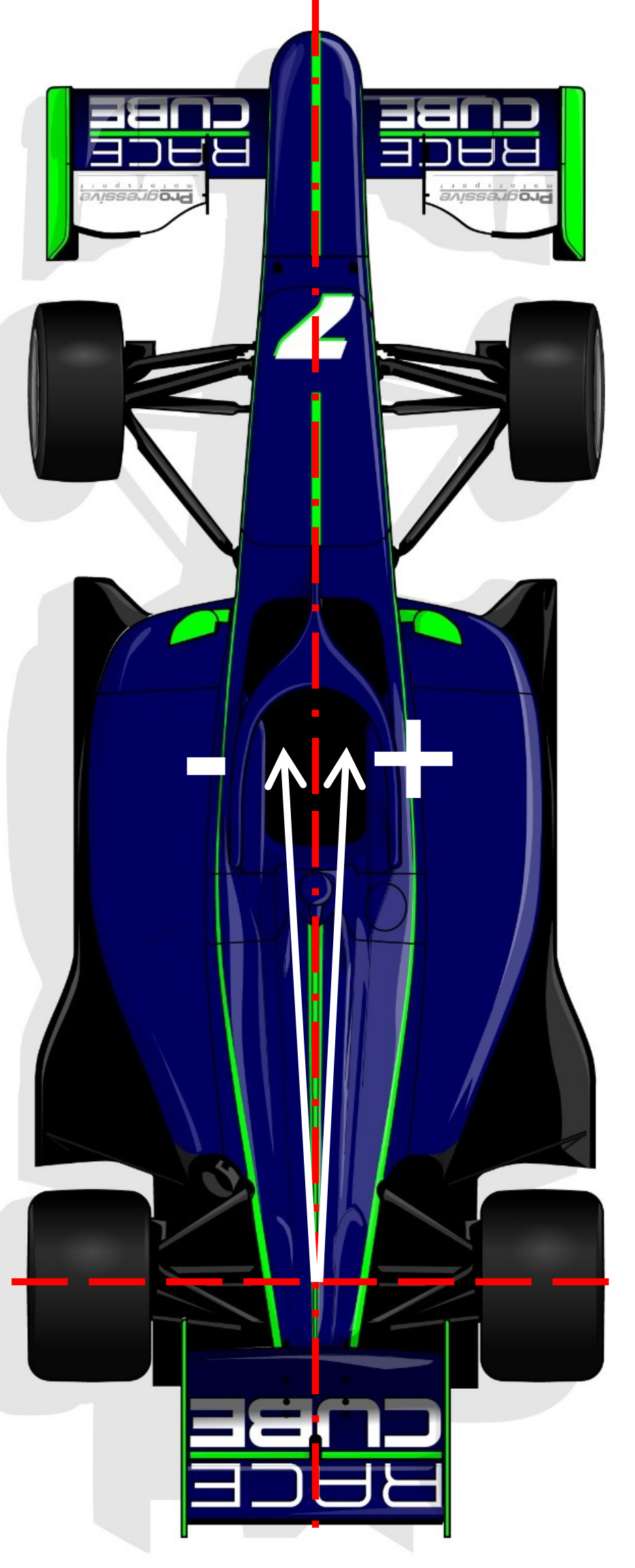
Thrust Angle
Also calculated is the thrust angle; the vehicle's driving direction. If the thrust angle is greater than 10 mins, we recommend adjusting the rear toe angles to align symmetrically about the Chassis centreline reference, keeping the same total toe angle as calculated or required. i.e. make the thrust angle coincident with the Chassis centreline reference with equal rear left and right toe angle either side of it. The front toe angles will now need to be adjusted to suit, to prevent the steering wheel from ‘hanging’. Note: as is convention, clockwise is ‘+ve’ thrust angle; anticlockwise is ‘-ve’ thrust angle.
Note that the Chassis centreline reference is not necessarily the same as the Body centreline. The Chassis centreline is determined by the relative positions of all four tyres on the ground, whereas the body centreline is independent and may be skewed to it. Any misalignment can potentially have adverse aerodynamic effects on the car.
Rear axle reference: initial toe measurement output
Here you see the same calculated data presented relative to the Rear Axle reference or thrust angle. Note the total rear toe angle remains unchanged and the individual rear toe angles are now equal and opposite about the thrust angle direction; now shown as 0°. Toe-in is ‘+ve’ and toe-out is ‘-ve’. The same calculated front toe data from the Chassis centreline reference is now presented as an output relative to the thrust angle.
If the previously calculated thrust angle is less than 10 minutes, it may be acceptable to leave the rear toe angles unadjusted and accept a small misalignment with the Chassis Centreline. If so, adjust the front toe angles to the desired values of individual and total toe relative to this Rear Axle (or thrust angle) reference. See Toe & Alignment Adjustment and Theory sections. When doing so it is recommended that the steering wheel is centred and locked to ensure it cannot move and is straight relative to the driving direction i.e. the thrust angle direction.
A calculated thrust angle of less than approximately 10 minutes of a degree is unlikely to be noticed by most drivers. However, a professional driver may notice it and comment on it. If this is the case the rear toe angles should be adjusted for zero thrust angle.
Toe and alignment adjustment
It is important that the front and rear measurement scales are left unmoved from their original positions.
The car can be left on the ground, however IF it is easier for making adjustments, it can be jacked up or put on stands. The magic of the Cube means the car can be on the ground or in the air with the wheels in droop during the whole toe alignment and adjustment procedure. On the tablet, enter the FRONT and REAR TOTAL TOE TARGET values and distance to the scale indicated. Then press Align.
To adjust the front wheel toe, first set the steering wheel to be level and locked to ensure it cannot move, then for each FRONT wheel, adjust the vehicle’s track rods to adjust the toe to the indicated target value colour, letter and line that the laser crosses on the REAR measurement scales. Confirm when complete.
To adjust the rear wheel toe, for each rear wheel, adjust the toe link to the indicated target value colour, letter and line that the laser crosses on the FRONT measurement scales. Confirm when complete.
Toe set-up: rear axle reference
It is important that the front and rear measurement scales are left unmoved from their original positions. If it is easier to do so, the car can be jacked up or put on stands.
On the tablet, enter the FRONT TOTAL toe target value and distance to the scale indicated. Then press Align. To adjust the front wheel toe, first set the steering wheel to be level and locked to ensure it cannot move, then for each FRONT wheel, adjust the vehicle’s track rods to adjust the toe to the indicated target value colour, letter and line that the laser crosses on the REAR measurement scale. Confirm when complete. The toe angles will now be set relative to the Rear Axle reference i.e. relative to the thrust angle direction.
Camber
Camber can be measured separately and saved with the Setup. Attach Cube to the wheel adaptor and on the screen, press ‘Camber’. Take the reading, record it in the tablet and save it with the Setup.
Caster
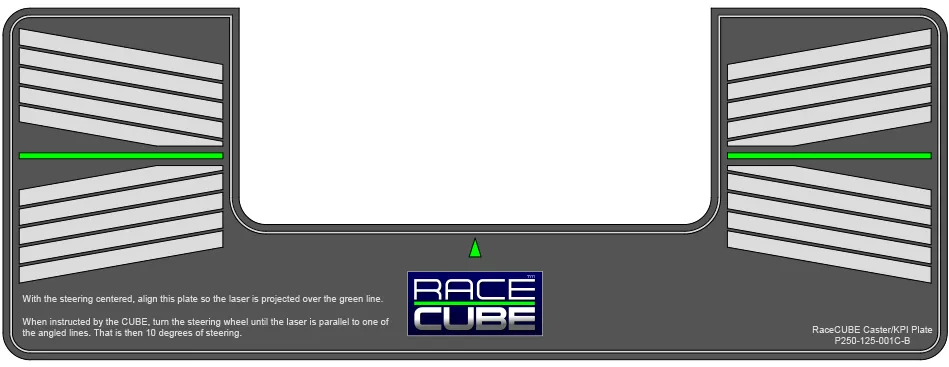
With the steering centred, align the caster plate so the laser is projected over the green line. Then when instructed by the Cube follow the instructions on the caster plate: turn the steering wheel until the laser is parallel to one of the angled lines. That is then 10 degrees of steering. Then input the results in the tablet. They will be stored with the Setup.
Note: the greater the accuracy when steering 10 degrees and levelling the bubble, the more precise the caster measurement will be.
King pin inclination (KPI)
With the steering centred, align the caster plate so the laser is projected over the green line. Then when instructed by the Cube follow the instructions to read the KPI. Then input the results in the tablet. They will be stored in the Setup.
Laser calibration
CAUTION: ONLY RE-CALIBRATE THE CUBE IF ABSOBUTLELY NECESSARY. IF YOU TRY A NEW CALIBRATION ALL PREVIOUS CALCULATIONS MAY BE VOID.
The laser is supplied pre-calibrated with an angle correction value to match a tablet with a specific Cube, but if re-calibration is ever required use the following procedure and enter the values in the tablet:
- Go to a room with at least 7m distance between walls
- Put a measuring tape on the floor extended over 7m
- Place the Y- adapter (3 legs) centrally over the 3.5m mark
- Place the Cube on the adapter with the screen pointing ahead (i.e. away from you when looking down)
- Looking down, you should see the battery cover and be able to read the label. It should have the same orientation as shown by the image to the right
- Using a non-reflective rule, measure the height of the laser at the 0mm (left) position and 7000mm (right) position on the tape measure
- Record the measurements in the “0 Degree” boxes on the tablet
- Holding the Y-adapter firmly on the ground and in the same position, rotate the Cube 180deg (with label now upside-down), measure again and record the results in the boxes on the tablet
- Press Calibrate
The Cube is now calibrated with an angle correction value shown on the SETTINGS page on the tablet. Once calibrated, do not use this tablet with any other Cube.
Theory
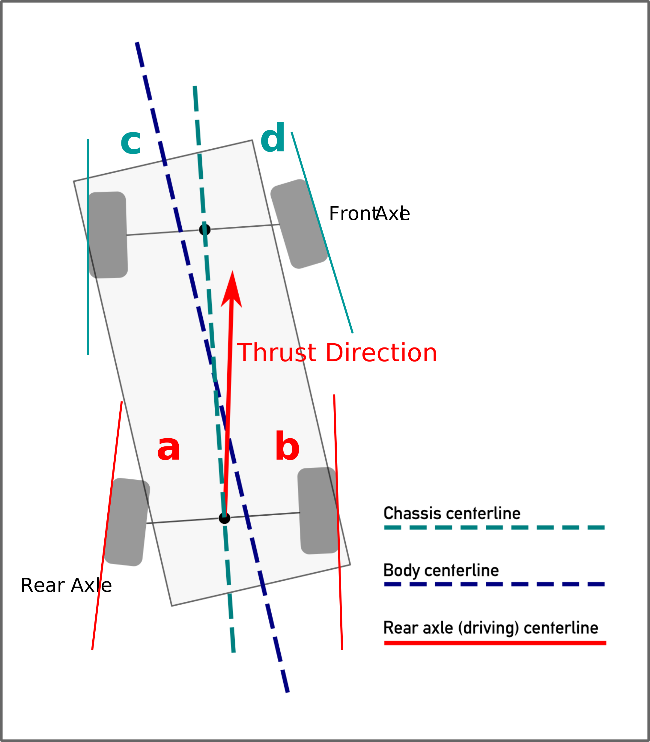
Through its inventive software and algorithms, RACECUBETM will first calculate the Chassis Centreline of the vehicle. Note, this is the ‘effective’ longitudinal centreline of the vehicle as determined by the wheels on the road. This is not necessarily the same as the Body Centreline which may for one reason or other be built slightly skewed to this Chassis Centreline.
RACECUBETM is able to calculate each of the front and rear wheel’s individual toe angle (c&d, and a&b) relative to the Chassis Centreline and also the total toe angles i.e. the included toe angles at the front axle and rear axle.
The driving direction of the vehicle is determined by the rear axle wheel alignment relative to the Chassis Centreline. This Rear Axle reference is also calculated by RACECUBETM i.e. the thrust angle is determined by bisecting the total toe angles (a plus b divided by 2) seen at the rear axle such that there is zero rear tyre slip. This is true for rear wheel drive vehicles and front wheel drive vehicles.
If the calculated thrust angle is in the region of 5 minutes of a degree, you can use the Chassis centreline reference to adjust the front toe angles as the misalignment is unlikely to have a perceptible effect for most drivers.
If the calculated thrust angle is between 5 and 10 minutes of a degree, the theory can be looked at from two perspectives: 1) If the calculated thrust angle is under 10 minutes, then it may be acceptable to adjust the front toe angles using the Rear Axle Ref. i.e. the vehicle will crab slightly but the steering wheel can be centred relative to the driving direction. OR 2) If the calculated thrust angle is greater than 10 minutes then the recommendation would be to adjust the two rear wheel toe angles (keeping the same total rear toe) to realign the thrust angle to be coincident with the Chassis centreline. With the steering wheel set to be level, the front toe angles should then be adjusted to the Chassis centreline reference or indeed to the adjusted Rear Axle reference which will now be the same thing.
General information
RACECUBETM is a Trademark of Aether Vehicle Technologies Ltd (Company No. 14877608)
The battery supplied with RACECUBETM is a 9v PP3 battery with 1.2Ah capacity. Any replacement 9v PP3 style battery will be sufficient but its working life will be reduced if not at this capacity. A typical household battery brand will be around 0.7Ah and will therefore only last about half as long.
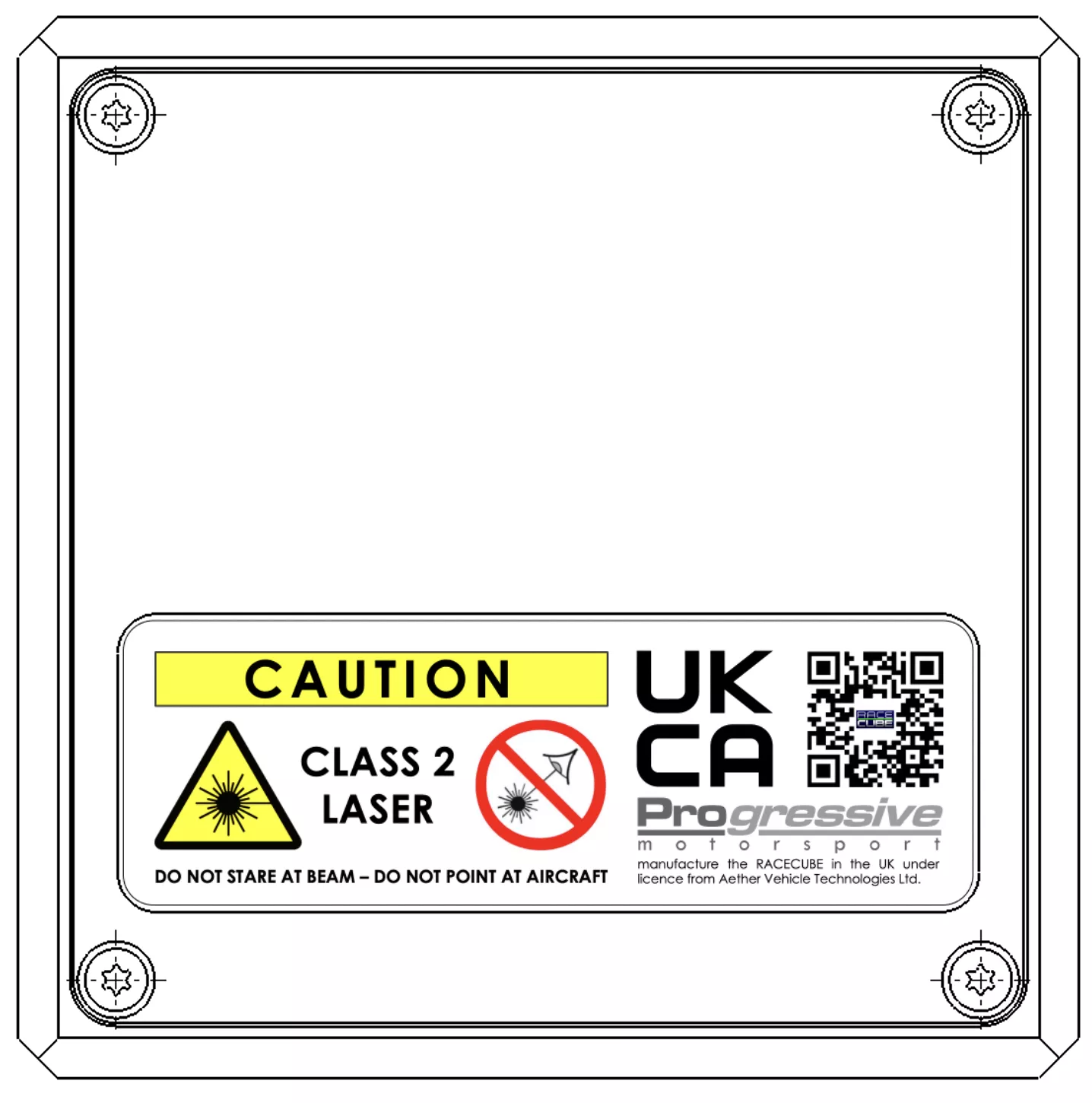
The 9v PP3 battery can be accessed by removing the cover panel shown on the right. Remove the 4 countersunk bolts using the tool provided. With the cover removed, the battery can be carefully extracted from the Cube, unplugged and replaced with new.
Whilst replacing the battery please be careful as there are exposed and delicate electrical components inside the Cube. Please make sure the battery cable does not get trapped when replacing the cover. Note the orientation of the warning sticker as if this cover panel is placed upside down then the felt pads that retain the battery will stop the lid from closing properly. Do not overtighten the bolts.
As with all batteries, they can be dangerous if mishandled or exposed to extreme temperatures. They can leak or even explode under certain circumstances.
Please dispose of and handle used batteries in a safe and appropriate manor.
A digital version of the instruction manual can be found by taking a photograph of the QR code (found on the battery cover and shown here on the right) with a mobile phone. Further instructions, warnings and recommendations can be found there.
Do not remove the cover panel shown on the right as it could affect the calibration. The 9v PP3 battery is accessed via the other panel shown above. There are no user serviceable items behind this cover panel.
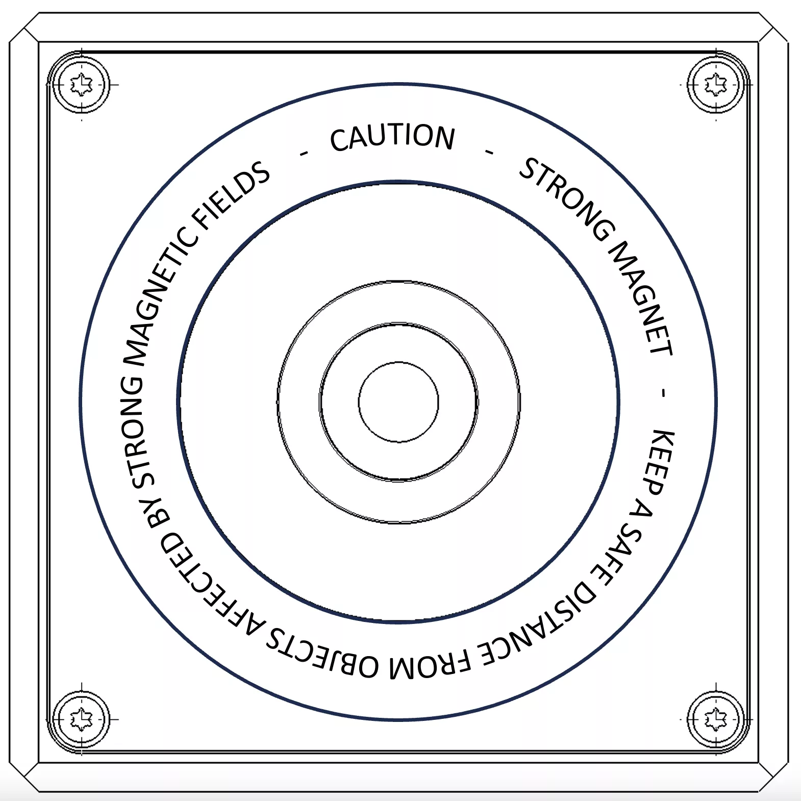
CAUTION – This panel and other RACECUBETM accessories contain very powerful neodymium magnets and interaction with metallic objects or other magnets may produce pinch and crush hazards.
Safety information
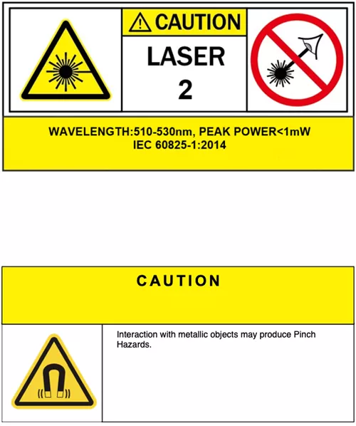
The laser used in RACECUBETM is classified as a Class 2 (or Class II) laser. The output power of a Class 2 laser is below 1 milliwatt. All Class 2 lasers emit visible light only and are relatively weak. They would not normally harm an eye unless a person deliberately stared into the beam. Laser protective eyewear is normally not necessary. A Class 2 laser is not a skin or materials burn hazard. However, even a Class 2 laser can be a distraction, glare or flash blindness hazard for pilots and drivers. NEVER aim any laser towards an aircraft or vehicle that is in motion. This is unsafe and is illegal – you could be arrested and jailed.
ONLY ALLOW USE OF RACECUBETM BY RESPONSIBLE PERSONS. It is not a toy. Children can safely use Class 2 lasers only with continuous adult supervision.
The RACECUBETM and its accessories contain extremely powerful neodymium magnets. Interaction with metallic objects may therefore produce pinch and crush hazards. The Pull Force of the large ring magnets is just under 10kg each.
Under no circumstances should children be allowed to handle powerful magnets such as these.
Keep a safe distance between other magnets and all objects that can be damaged by magnetism including heart pacemakers, mechanical watches, CRT monitors and televisions, credit cards, diskettes and other magnetically stored media. The operation of heart pacemakers will be affected by the close proximity of a magnet.
The neodymium magnets and the RACECUBETM accessories are coated with Nickel which can cause an allergic reaction in some people who are exposed to long term contact with Nickel.
Please note that such issues are usually due to the wearing of Nickel-plated products which are in close proximity to the skin for prolonged periods of time. E.g. Jewellery. There should not be an issue with the handling of the RACECUBETM or associated accessories, but the user is urged to seek medical advice if an adverse reaction occurs.
Disclaimers
Please note that RACECUBETM is a set-up tool. It measures various aspects of the vehicle geometry and informs the user of the current settings. Its accuracy and repeatability is down to the user. Mishandling by the user can cause misleading and incorrect measurements.
Users must decide for themselves which setting or target value is correct for the vehicle they are working on. RACECUBETM is merely a tool to help the user achieve their required target value.
RACECUBETM, Aether Vehicle Technologies Ltd, Progressive Motorsport Ltd and any other company associated with the design and manufacture of RACECUBETM accept no liability for the resulting set-up and handling of the vehicle.
RACECUBETM, Aether Vehicle Technologies Ltd, Progressive Motorsport Ltd and any other company associated with the design and manufacture of RACECUBETM are not responsible for damages that result from the use of our product on your vehicle.
Never disregard professional engineering advice or override manufacturer recommended set-up parameters for your vehicle.
RACECUBETM, Aether Vehicle Technologies Ltd, Progressive Motorsport Ltd and any other company associated with the design and manufacture of RACECUBETM do not offer or suggest vehicle set-up target values. This product is simply a tool to aid the user in measuring their own vehicle. The user must satisfy themselves that the target values used on the vehicle are suitable and correct for the intended purpose.