

Cube vector output
RACECUBE™ Pro: Only CUBE Vector Output is obtainable.
CUBE Vector Results Output
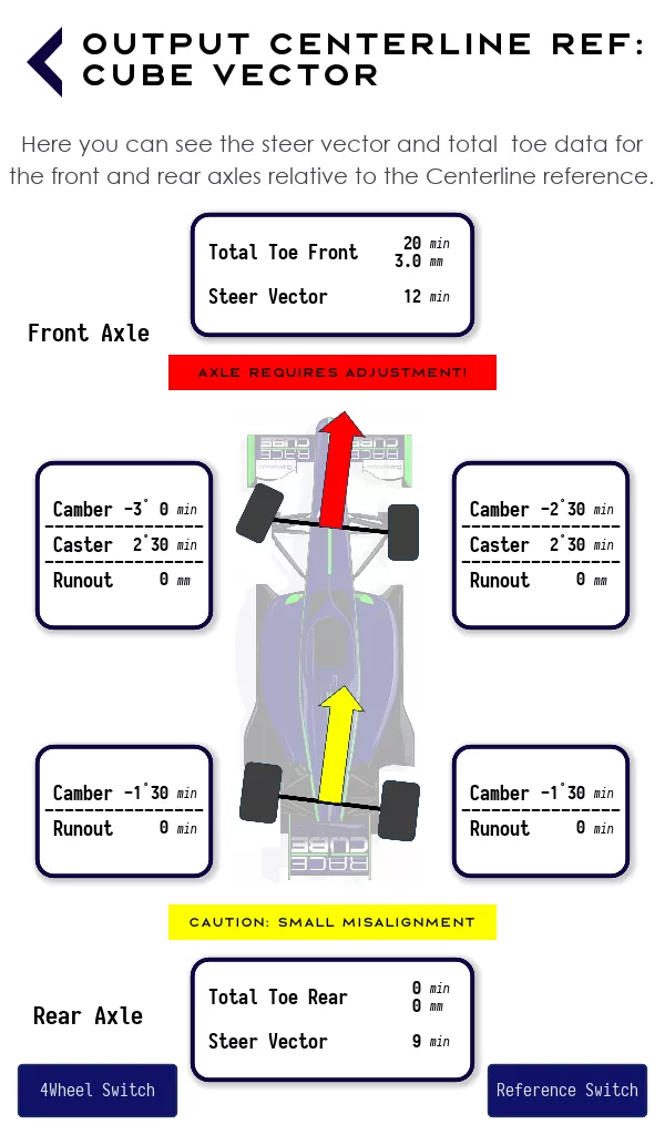
Centreline Reference: Initial Toe Measurement Output
Here you see total toe and steer vector (steer angle) information for both the front and rear axles relative to the calculated Chassis centreline reference of the vehicle. As with standard convention, toe-in is ‘+ve’ and toe-out is ‘-ve’.
CUBE Vector
The CUBE Vector output uses the same alignment results as the 4Wheel output toe data but presents them as two distinct parameters: the total toe and the steer vector (or steer angle) for each axle.
For many setups, these two parameters are all that is needed to visualize the overall effects of where the independent wheels are pointing. For each axle, combining the individual left and right wheel alignment results into a resultant total toe and steer vector provides a very easy way of determining whether the setup is within acceptable limits or not. The results are aided graphically by a red, yellow and green ‘traffic light’ system making it very easy to see whether the axles require adjustment or not.
Green = Alignment OK (i.e. steer vector <= + 5 or >= -5 mins)
Yellow = CAUTION!: Small Misalignment( i.e. steer vector < +10 mins or > -10 mins)
Red = Axle Needs Adjustment! ( i.e. steer vector > +10 mins or < -10 mins)
Physically, the total toe influences the vehicle dynamics characteristics for the car: e.g. tyre temperature and pressure; suspension kinematics; understeer/oversteer; steering response and rolling resistance. In other words, with the total toe you simply set and affect the vehicle’s dynamic behaviour. The CUBE Vector (or steer angle) is simply the steer angle of the axle. For many setups (oval racing being an exception) it is not generally necessary to visualize where the independent wheels are pointing. If the steer angle of the axle is zero, then it is aligned and pointing straight in relation to the Chassis centreline (or in reference to the rear axle, if you chose that reference mode). Any deviation from zero means that the axle is not pointing straight and will have a net steering effect i.e. the axle is misaligned.
The simplicity of the CUBE Vector output is that the information very clearly displayed is all that is needed to be known i.e. the total toe (whether toe-in or toe-out) and the steer vector of each axle. This information will indicate whether the car is set up with the right total toe, giving the desired vehicle dynamic behaviour, and whether the wheels are properly aligned for the car to drive straight.
For each axle, if the steer vector is outside of acceptable limits, the Toe Adjust function can be used to easily adjust the steer vector (and if necessary the total toe angle) to align symmetrically about the Chassis centreline reference. This may be to keep the same total toe angle as calculated or a new one if required. Such re-alignment will make the steer vector coincident with the Chassis centreline reference with equal left and right toe angle either side of it.
If the indicated rear axle steer vector is yellow (i.e. less than 10 mins of a degree) it may be acceptable to leave the rear steer vector unadjusted and accept a small misalignment with the Chassis centreline. If so, adjust the front total toe to the desired value of total toe and front steer vector relative to this rea axle vector. See Toe & Alignment Adjustment and Theory sections. When doing so it is recommended that the steering wheel is centred and locked to ensure it cannot move and is straight relative to the driving direction i.e. the thrust angle direction.
A rear steer vector of less than approximately 10 minutes of a degree (indicated by a yellow arrow) is unlikely to be noticed by most drivers. However, a professional driver may notice it and comment on it. If this is the case the rear toe angles should be adjusted for zero rear steer vector angle.
Note that the Chassis centreline reference is not necessarily the same as the car Body centreline (Link to Theory tab). The Chassis centreline is determined by the relative positions of all four tyres on the ground, whereas the body centreline is independent and may be skewed to it. Any misalignment can potentially have adverse effects on the vehicle dynamics, aerodynamics and designed elasto-kinematics of the car.
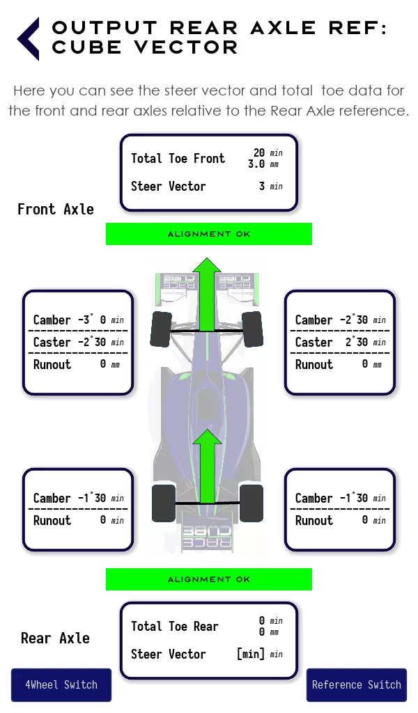
Rear Axle Reference: Initial Toe Measurement Output
Here you see the same calculated data from the CUBE Vector centreline reference but now presented relative to the Rear Axle reference direction or rear steer vector i.e. the reference frame whereby the rear axle steer vector is zero.
Note the total rear toe angle remains unchanged and is now equal and opposite about the rear steer vector direction. Toe-in is ‘+ve’ and toe-out is ‘-ve’. The same calculated front axle total toe data from the Chassis centreline reference is now presented as an output relative to the rear steer vector. By definition, the rear axle steer vector is now zero and the front axle steer vector is now relative to it.
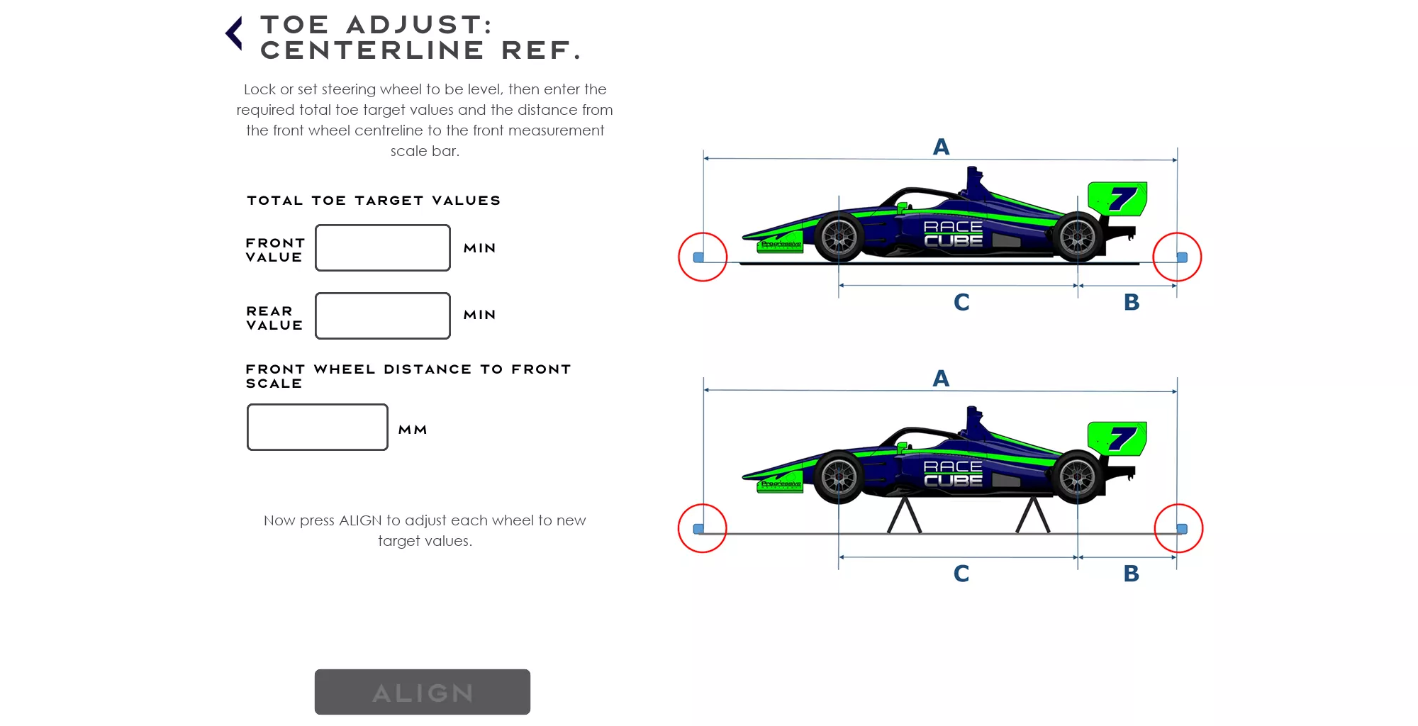
Toe Adjust: Centreline Reference
It is important that the front and rear measurement scales are left unmoved from their original positions.
The car can be left on the ground, however IF it is easier for making adjustments, it can be jacked up or put on stands. The magic of the Cube means the car can be on the ground or in the air with the wheels in droop during the whole toe alignment and adjustment procedure. It is also the case that the car can be measured on the ground and then, if it is more convenient, adjusted off the ground. This is because once the car has been measured the software ‘knows’ the relative positions of the wheels and therefore by how much they may need to be adjusted.
On the tablet, enter the FRONT and REAR TOTAL TOE TARGET values and distance to the scale indicated.
To adjust the front wheel toe, first set the steering wheel to be level and locked to ensure it cannot move. Record the Number and Letter where the laser now crosses the REAR bar and then press Calculate to see the new target i.e. where the laser needs to be adjusted to. Then for each FRONT wheel, adjust the vehicle’s track-rods to adjust the toe to the indicated target Number and Letter value that the laser crosses on the REAR measurement scales. Confirm when complete.

To adjust the rear wheel toe, first record the Number and Letter where the laser now crosses the FRONT bar and then press Calculate to see the new target i.e. where the laser needs to be adjusted to. For each rear wheel, adjust the toe-link to the indicated target Number and Letter value that the laser crosses on the FRONT measurement scales. Confirm when complete.

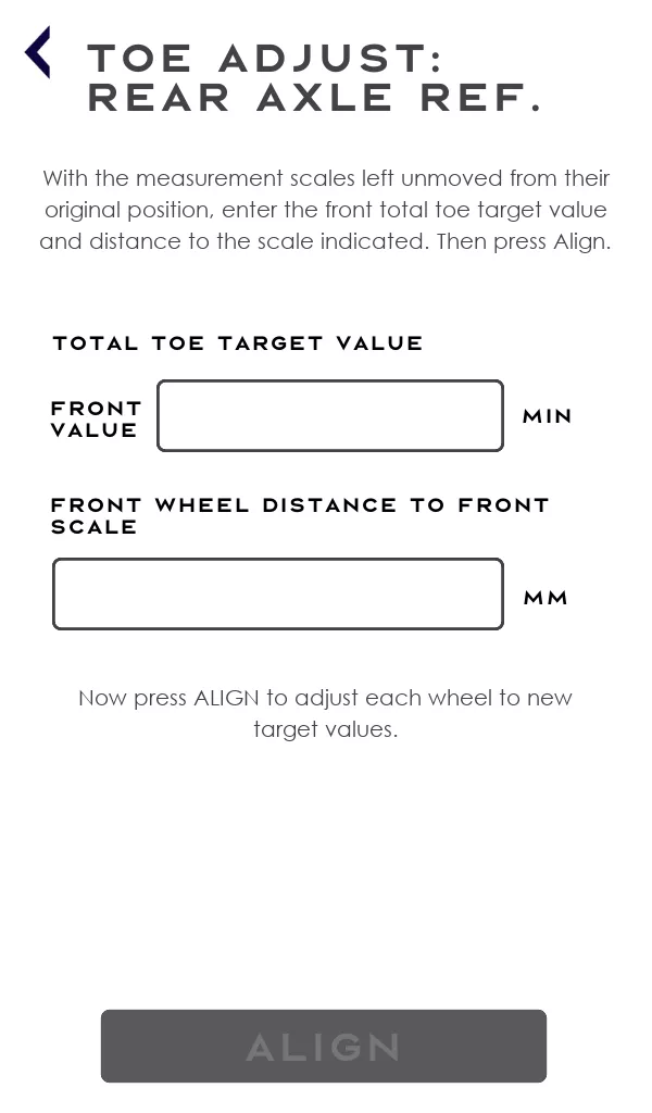
Toe Adjust: Rear Axle Reference
It is important that the front and rear measurement scales are left unmoved from
their original positions. If it is easier to do so, the car can be jacked up or put on stands.
On the tablet, enter the FRONT TOTAL toe target value and distance to the scale indicated. Then press Toe Adjust (Rear Axle Ref).
To adjust the front wheel toe, first set the steering wheel to be level and locked to ensure it cannot move. Record the Number and Letter where the laser now crosses the REAR bar and then press Calculate to see the new target i.e. where the laser needs to be adjusted to. Then for each FRONT wheel, adjust the vehicle’s track-rods to adjust the toe to the indicated target Number and Letter value that the laser crosses on the REAR measurement scale. Confirm when complete. The front toe angles will now be set relative to the Rear Axle reference i.e. relative to the thrust angle direction.
Set-up recommendations when adjusting toe alignment
Like any other alignment system, it is first necessary to fix the steering rack so that it doesn‘t move when working on the track-rods. Usually this is done by first clamping the steering wheel and setting it to be level in the straight-ahead position.
If you don‘t do this, any force you put into the suspension, when loosening or tightening the nut on the track-rod - or if you touch the tyres - will result in the wheels moving slightly. That is not only true if the car is on the lift-jack or stands but it will also happen when the car is on the ground on its tyres. When you apply torque to the track-rod nuts to tighten them properly, the track-rod will ‘stretch’ marginally and you will see that the toe angle will have changed marginally too (by approximately 2 minutes).
With RACECUBE™, you will see after tightening that the laser has moved slightly on the scale bars. To compensate for this effect, to get the exact target value, we recommend turning the track-rod threads a small amount past (or before) the theoretically exact point (depending on whether the track-rods are in front or behind the axle centre), and then tighten the track-rod nut. By doing this, the laser will fall back to the optimum target as calculated by the software.
Camber
Camber can be measured separately and saved with the Setup. Attach the Cube to the wheel adaptor and on the screen, press ‘Camber’. Take the reading, record it in the tablet and save it with the Setup.
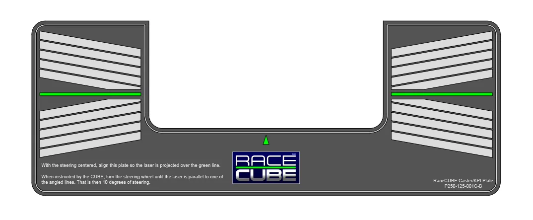
Caster
With the steering centred, align the caster plate so the laser is projected over the green line. Then when instructed by the Cube follow the instructions on the caster plate: turn the steering wheel until the laser is parallel to one of the angled lines. That is then 10 degrees of steering. Then input the results in the tablet. They will be stored with the Setup. [Add Hi -Res Caster plate graphic p8 of A5 booklet]
Note: the greater the accuracy when steering 10 degrees and levelling the bubble, the more precise the caster measurement will be.
King Pin Inclination (KPI)
With the steering centred, align the caster plate so the laser is projected over the green line. Then when instructed by the Cube follow the instructions to read the KPI. Then input the results in the tablet. They will be stored in the Setup.
We want to hear from you!
We welcome all enquiries and are keen to discuss our revolutionary new wheel alignment technology with you. Please get in touch and we'd be delighted to assist.
Call: +44 (0) 7899 961947
Email: info@racecube.uk